
 BETA
BETAThe embedded controller
In part 1, we looked at the communication between a Lenovo Thinkpad X230T laptop and battery, and discovered that there a challenge-response protocol used to authenticate ‘genuine’ Lenovo batteries. On the laptop side, this – and battery communication in general – is implemented in a component known as the embedded controller (EC).
The embedded controller is a low-power embedded microprocessor that could be considered part of the ‘autonomous nervous system’ of a laptop. The embedded controller helps to control background functions such as power management, temperature monitoring, fan speed control, etc., and may stay powered even when the system is switched off. For historical and pragmatic reasons the embedded controller is also usually the same microcontroller as the system keyboard controller.
The ACPI (Advanced Configuration and Power Interface) standard defines an interface that allows an operating system to interact with the embedded controller in order to monitor and configure its power management functions, however the implementation of the embedded controller is proprietary and completely up to the system vendor. It is not always even clear what chip is used for the embedded controller in any particular computer.
Searching online, a number of other people have been interested in modifying ThinkPad embedded controller firmware to alter keyboard and fan behaviour. In earlier ThinkPad laptops which use Renesas H8S microcontrollers, the firmware has been analysed in detail and even modified successfully.
After downloading and poring over the BIOS update image for my X230T, I found something that looked like EC firmware at offset 0x500000 in the file $01DA000.FL2: the data that followed was 192KB in size and contained the string “GCHT25WW” which is the embedded controller firmware version. I tried disassembling this firmware image as Renesas H8S instructions but with no success. Either I was looking in the wrong place or Lenovo was no longer using the H8S.
After some more Internet searching I found a link to purported “Dasher 2” (X230) schematics (this is not exactly the same as my laptop, which is an X230T, but is very similar). These schematics show the embedded controller being the Microchip MEC1619. The MEC1619 contains an ARC625D microprocessor and 192KB of flash memory, which indeed matches the 192KB size of the suspected firmware image. I now tried disassembling the firmware image according to the ARC625D instruction set (ARCompact) and sure enough: these were definitely ARC instructions, and the embedded controller in my laptop was almost certainly a MEC1619.
I could not find the full datasheet of the MEC1619 online, however apart from the ARC processor core it is similar to the MEC1322 (which uses an ARM core) and the MEC140x/MEC141x (which uses a MIPS core). I found it useful to refer to those datasheets to understand the general architecture and peripherals available. (There even seem to be similarities in the memory maps: for example, the ACPI EC Interface is located at 0xF0D00 on the MEC140x and at 0xFF0D00 on the MEC1619.)
Locating the battery authentication
After successfully disassembling the EC firmware as ARC instructions, I searched through the disassembly for the command sent in the first authentication sequence (0x3c hexadecimal, or 60 in decimal). The value 60 occurred several times but I found one very good candidate:
  1d0e8:      c9 70                mov_s      r0,r14
  1d0ea:      0a d9                mov_s      r1,10
  1d0ec:      3c da                mov_s      r2,60
  1d0ee:      04 db                mov_s      r3,4
  1d0f0:      18 f1                b_s        0x1cf20

  1cf20:      0d ff                bl_s       0x1cb54
Here r2 is set to 60 (0x3c) and r3 is set to 4, which is indeed the length of the data sent with the first authentication command. Searching for other branches to the same location, nearby I also found:
  1d25e:      c9 70                mov_s      r0,r14
  1d260:      0a d9                mov_s      r1,10
  1d262:      27 da                mov_s      r2,39
  1d264:      bd 04 ef ff          b.d        0x1cf20
  1d268:      11 db                mov_s      r3,17
Here r2 is set to 39 (0x27 in hexadecimal – the second authentication command) and r3 is set to 17, which is indeed the length of the data sent with the second authentication command.
(If you’re wondering about this last code sequence and the last move instruction being after the branch, the ARC architecture, like MIPS and others, has branch delay slots: the b.d instruction executes the instruction following the branch while the branch is being taken, whereas a regular b or b_s instruction nulls it out. If this makes no sense to you, don’t worry about it. The _s after instruction names refers to the ‘short’ 16-bit encoding of the instruction and has no effect on the function of the instruction.)
So now I had a good lead for the part of the EC code that was querying the battery. I further analysed the code around that point, and this function indeed turned out to be a state machine that queried the battery. The relevant states look approximately like this:
state 7: start write command 0x3c (with 4-byte challenge)
state 8: check success, retry if necessary
state 9: unknown
state 10: start read command 0x3c
state 11: check success, retry if necessary
state 12: validate battery response
state 13: choose challenge number
state 14: start write command 0x27 (with 17-byte challenge)
state 15: check success, retry if necessary
state 16: unknown (same as state 9)
state 17: start read command 0x28
state 18: check success, retry if necessary
state 19: validate battery response
state 20: set battery status
At this point, I knew roughly what I had to patch (states 12 and 19 in particular). So far so easy, but this was only the start. The difficult part is that the firmware has checksums to guarantee integrity that I would have to update after making any changes.
I extracted the embedded firmware images from the 20 past BIOS versions for the X230T (which contained 8 different embedded controller firmware versions in total) and compared them to find areas that might be checksums. The last four bytes of the EC firmware image clearly appeared to be a checksum, and there were some other locations that consistently varied as well. I guessed (correctly) that if I programmed an image with the wrong checksums the EC would fail to boot and I would have a brick on my hands, so trial and error was not a very good option.
For the last four bytes, I experimented with various 32-bit checksum algorithms (summing up the words, exclusive or’ing the words, CRC32, Adler32, etc.) without success. I looked at the earlier work mentioned above that had successfully analysed the Renesas H8S firmware, and that firmware used simple 16-bit checksums. In fact, a 16-bit checksum did work: the last two bytes of the image were chosen so to make a simple 16-bit sum of the whole image add to zero. But I couldn’t figure out how to calculate the other two bytes of the last four bytes. All four bytes changed together in firmware updates, so there was likely still some secret to be discovered.
There was something else interesting: it appeared that parts of the EC firmware image were encrypted. After receiving the authentication response from the battery, the routine called a validation function, but that function (and surrounding code) looked like garbage when disassembled:
  1d168:      ee 0f af f2          bl.d       0x2954 ; validate

   2954:      57 8b                ldb_s      r2,[r3,23]
   2956:      9f a1                st_s       r12,[r1,124]
   2958:      5c 6a                asr_s      r2,r2,4
   295a:      54 2b 5f ed          vadd2h.f   blink,r51,53
   295e:      73 2f 40 f7          qmpywhu.f  r0,pcl,29
   2962:      e9 3d a4 eb          ???.n.f    r53,r53,46
   2966:      26 04 86 d1          bnc        0xfffa5d8a
(This disassembly makes no sense, it cannot possibly be what the processor executes.)
Passing that part of the firmware image through the Linux ‘ent’ utility, the entropy was over 7.9 bits/byte compared to the rest of the image which had an entropy of about 5.9 bits/byte, making it very likely that that encryption was involved (high entropy could also indicate compression, but that wouldn’t make sense here as there is a branch directly into the middle of it). Also, from a certain address onwards, the rest of the encrypted data changed completely in every firmware revision, suggesting cipher block chaining with a most likely block size of 64 bits.
But the EC firmware executes directly out of flash memory, and the MEC1619 datasheet says nothing about the processor supporting decryption on-the-fly (which would be difficult to implement in any case). I assumed therefore that the EC code must be stored in flash memory in decrypted form, while the firmware update image is partially encrypted to protect it from prying eyes like mine. Additionally, if the second half of the checksum was calculated on the decrypted version rather than the encrypted version I had, this would explain why I was finding it hard to determine the checksum algorithm.
A digression on x86 system architecture
I started looking into how the process of updating the EC firmware works, in the hope that it would give me more insight into how the flash memory was accessed. In order to understand the firmware update process, it is useful to have some background knowledge about how the CPU and EC communicate.
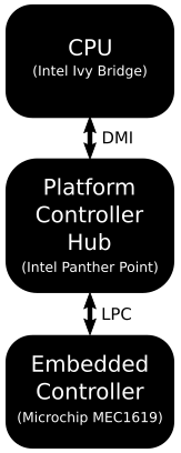
At a physical level, the embedded controller is connected to the LPC bus. The LPC bus is like the cassette tape deck of the modern laptop: it is the last remaining remnant of the legacy ISA bus that preceded PCI that preceded PCI-Express. The LPC bus is still used for a number of miscellaneous devices for which speed is not critical. The physical topology in the X230T looks like this:
The ACPI standard defines a standard access method for communicating with the embedded controller. This access method involves writing commands to one I/O port and reading/writing data from/to another I/O port (on x86 these I/O ports are generally I/O ports 0x62 and 0x66). There are two main commands defined: Read Embedded Controller (0x80) and Write Embedded Controller (0x81). These commands allow reading or writing one of 256 locations in the embedded controller, each 8 bits in size. (For completeness, I will mention that there are a few other minor commands defined in the ACPI specification, but those are not implemented by the Thinkpad EC.)
It is possible to read and write these EC locations in Linux using the ec_sys kernel module and the ec_access utility:
$ sudo modprobe ec_sys
$ sudo ./ec_access -r
     00 01 02 03 04 05 06 07 08 09 0A 0B 0C 0D 0E 0F
00:  a7 09 a0 c2 00 86 05 00 00 00 47 00 00 03 80 02
10:  00 00 ff ff d0 fc 00 01 7b ff 01 f0 ff ff 0d 00
20:  00 00 00 00 00 00 00 b8 00 00 00 00 e8 00 00 80
30:  00 00 00 00 31 04 00 00 a4 00 20 10 00 50 00 00
40:  00 00 00 00 00 00 14 c6 02 84 00 00 00 00 00 00
50:  00 80 02 0c 00 01 02 03 04 05 06 07 f5 1b 76 1c
60:  6e 95 f9 57 05 00 00 00 00 00 00 00 00 00 00 00
70:  00 00 00 00 08 00 00 00 2d 00 00 00 00 00 00 00
80:  00 00 05 06 00 00 03 00 00 00 00 00 00 00 2b 00
90:  00 00 00 00 00 00 00 00 00 00 00 00 00 00 00 00
A0:  c0 00 c0 00 ff ff 64 00 00 00 3e 31 ff ff a0 02
B0:  00 00 00 00 00 00 00 00 00 00 41 05 01 18 01 00
C0:  00 00 00 00 00 00 00 00 01 41 00 00 00 9b 00 00
D0:  15 c0 00 00 00 00 00 00 00 00 00 00 00 00 00 00
E0:  00 00 00 00 00 00 00 00 11 40 da 16 e4 2e 44 03
F0:  47 43 48 54 32 35 57 57 1c 67 63 0d 00 00 00 00
What are these 256 bytes? Well, in actual fact, this is entirely implementation-specific. ACPI only defines the access method, it does not define any of the 256 locations that might be presented by the EC. You can see the embedded controller version (“GCHT25WW”) at offsets f0-f7, but other than that this data is pretty opaque without having further information.
In order to work out what registers to access to perform a desired function – for instance, querying the system battery – the operating system uses ACPI tables. The ACPI tables are defined by the system manufacturer, in this case Lenovo, and the BIOS passes these tables to the operating system at boot. We can dump and decode the ACPI tables from a live system using the following commands (make sure you do this in a new directory as it will dump out a lot of files):
  $ sudo acpidump -b
  $ iasl -d *.dat
To query a system battery, the ACPI specification defines that the operating system should invoke a method called _BST (short for Battery Status). Below I’ve included an extract from my Thinkpad X230T’s ACPI tables which shows how _BST is implemented on the Thinkpad. (I have omitted much of it for readability, if you are interested in more detail [God help you] I encourage you to dump your own system’s tables.)
Device (EC)
{
    ...
    // This part defines how to access the EC
    Name (_CRS, ResourceTemplate () // Current Resource Settings
    {
        IO (Decode16, 0x0062, 0x0062, 0x01, 0x01) // port 0x62
        IO (Decode16, 0x0066, 0x0066, 0x01, 0x01) // port 0x66
    })
    ...
    // This part defines symbolic names for the EC registers
    Field (ECOR, ByteAcc, NoLock, Preserve)
    {
        ...
        Offset (0x38),
        HB0S,   7, // Battery 0 Status @ EC 0x38 bits 0..6
        HB0A,   1, // Battery 0 Active @ EC 0x38 bit 7
        HB1S,   7, // Battery 1 Status @ EC 0x39 bits 0..6
        HB1A,   1, // Battery 1 Active @ EC 0x39 bit 7
        ...
        HIID,   8, // Battery Page Select @ EC 0x81
        ...
        SBVO,   16, // Battery Voltage @ EC 0xAA-0xAB
        ...
    }

    // Function containing common code for both batteries
    Method (GBST, 4, NotSerialized)
    {
        ...
            HIID = Arg0   // Write Battery Page Select
            Local3 = SBVO // Read Battery Voltage
            // More code here, eventually returning status
        ...
        Return ...
    }

    Device (BAT0) // Battery 0
    {
        ...
        Method (_BST, 0, NotSerialized)  // _BST: Battery Status
        {
            ...
            // Read Battery 0 Status (HB0S), call GBST function
            Return (GBST (0x00, HB0S, ...))
        }
    }
    Device (BAT1) // Battery 1
    {
        ...
        Method (_BST, 0, NotSerialized)  // _BST: Battery Status
        {
            ...
            // Read Battery 1 Status (HB1S), call GBST function
            Return (GBST (0x10, HB1S, ...))
        }
    }
    ...
}
Ultimately, a BAT0._BST invocation will read and write EC registers such as Battery 0 Status (0x38) and Battery Voltage (0xAA and 0xAB), but note that these registers are implementation-specific, they are not defined in the ACPI standard.
(If you’re wondering, the language is here ACPI Source Language [ASL], which is compiled to ACPI Machine Language [AML] and executed at runtime by a bytecode interpreter in the operating system. If this seems very complicated, it is: in a past life, I worked with microkernels, and the size of the kernel jumped by an order of magnitude when we implemented ACPI. The ACPI abstraction is very powerful, however, freeing the operating system from having to know about platform implementation details.)
The EC update process
Now let us return to the process of updating firmware. There are two stages: first, the Lenovo update program is run (from Windows or DOS) and it writes the firmware update image to a special area, then the system reboots to BIOS and the BIOS applies the necessary updates (to BIOS and/or embedded controller firmware). So the actual embedded controller update is performed by BIOS.
The ThinkPad has a BIOS that is implemented according to the UEFI specification. A detailed description of UEFI would take a whole book, however briefly, it defines a modular BIOS which consists of many separate executable modules. For example, there may be a module to initialize the video card or a module to initialize the keyboard. These modules are in Portable Executable format, which is the same format used for Windows executables, although clearly the environment is far more primitive. The UEFI loader – the core of the boot process – calculates the dependencies between the modules and then runs each module in the most sensible dependency order. Each module takes a pointer to a EFI system table which contains pointers to all the system services provided by the UEFI infrastructure.
There are a number of tools around that can pull apart a UEFI ‘capsule’ (firmware update image). I used UEFITool.
The core of the EC update process is implemented in a BIOS module called EcFwUpdateDxe.efi. I mentioned above that an ACPI-compatible embedded controller exports two commands, 0x80 (read) and 0x81 (write). It turns out that early in the boot process the Lenovo EC exports an additional command, 0xaf (upload code). (Later in the boot process this command is irreversibly disabled until the next reboot: this is in fact a good thing for security as silent updating of the EC by viruses could be very dangerous. A similar security mechanism also applies for updating the main BIOS image.)
EcFwUpdateDxe.efi, invoked early in the boot process, uses EC command 0xaf to upload a small ‘flasher’ program to the embedded controller. The purpose of the flasher program is to accept commands from the host to erase and program the internal flash memory of the EC. Importantly, the flasher program runs from EC RAM so that the internal flash memory can be reprogrammed (normally, the EC runs directly from internal flash memory, which would make it impossible for it to reprogram itself).
The update process sends the EC firmware image to the flasher program in the original partially-encrypted form. The flasher program then presumably decrypts blocks before it programs them.
So surely we can work out the decryption algorithm by disassembling the flasher program, right? Ah, but there’s a catch. The flasher program itself is encrypted! And it is decrypted by a function on the EC which is itself encrypted, at least in the firmware update image. So temporarily we are at an impasse.
Thanks be to Russian hackers
But remember that I hypothesised that the EC firmware is stored in flash memory in decrypted form. If we could read that flash memory via some side channel, we would presumably be able to extract the decryption function. As it turns out, the MEC1619 has a JTAG interface that can be used for programming and readback of its flash memory, as well as remote debugging of the ARC625D microprocessor. JTAG is a standard that is widely used by hardware folks for testing and programming chips; it consists of four to five pins: TCK (clock), TMS (mode select), TDI (data in), TDO (data out) and sometimes TRST (reset). (Technically JTAG is the name of the industry association and the interface is called a Test Access Port, but everyone I know calls the interface JTAG.)
Physically getting to the MEC1619 to access these pins is rather difficult and takes a fair bit of disassembly (I believe the MEC1619 is located under the ExpressCard slot). Happily, I did not need to do this: in Googling for MEC1619 JTAG I found a Russian forum where some dude had already connected up JTAG to his laptop’s MEC1619 embedded controller, and what’s more, posted the flash memory image on the forum. Sure enough, it was in decrypted form.
Now that I had a decrypted version of the EC code, including the decryption routine, it was only a matter of time before its secrets were revealed.
In part 3 we finally manage to solve the checksum puzzle and build a new embedded controller image… but then hit a few more challenges…

It is outrageous, that Lenovo tries to vendor-lock customers to buy their c**p.
I would love to have a list of companies using these kinds of dirty tricks to avoid EVER buying from them again.
Very interesting post!
> I would love to have a list of companies using these kinds of dirty tricks to avoid EVER buying from them again.
Almost all companies? I hope you are throwing away your iProducts. Check “MFI certified.”
The very 1st I know of was IBM who did “not recognize” the exact same Seagate HDD model (bought from ST for the official price) but only “its own” IBM-branded ST-HDD available for 3 times the ST-price.
That was back in 1990 in the PS/2 series.
I’ve got an x220 tablet and have also just run into this battery problem. Honestly, I wouldn’t have bought this laptop if I’d known about it – I thought ubuntu would keep me safe from DRM and coercive upgrades. Is there any chance this series of posts might end with a utility script to work around the problem? So that the bios skips running the DRM code?
Cheers
I’ll publish enough information/tools that it will be possible to replicate what I did, although at this point I’m not planning to release an easy ‘one click’ solution, I don’t really want to be responsible for end users bricking laptops… this series of posts is really more about delving into how it all works which I think is quite interesting.
> now, lemme just replace the battery and i’m ready to go…
*four days later*
> FFFFFFFFFFFFFFFFFFFFFFFFFFFFFFFFFFFFFFFFFFFFFFFFFFFFFFF
Yep, that’s pretty much how it went down 🙂
Fascinating stuff, I love seeing detailed analysis of all of the stuff we usually take for granted (or get aggravated at, in Lenovo’s case) in computers. It should be obvious but one doesn’t immediately think of a battery as something that would have firmware…
Sad that even batteries come with DRM now…
Interested in reading Part 3!
I have to say this stuff is great! I really enjoyed reading about how deep you are able to go with the hardware reverse engineering.
Can’t wait for the next part!
Great write up! I just read both part one and part two, I can’t wait for the next one.
Great article, not only interesting from technical perspective but also very well written and educational. Thank you very much.
I’m interested in how it goes on now, though… :-))
wow! amazing hw detective story! keep going!
Matt, this is excellent reading. Out of curiosity … you started this article series mentioning that you bought the replacement battery for upcoming holidays. I doubt you were able to fix all this before you went 😉 but how long did it take you to come to a solution? OK, I suppose this ends with a solution 🙂
This is a great article series, I can’t wait for it to be complete and successful, so then people can start building EFI-BIOS updates with that patch! This would be really awesome, especially for those devices that are out of warranty by now (which are practically all T/X *20 series models, and probably most T/X *30 series as well).
Someone explained to me a reason why Lenovo may have built this restriction into their machines. It goes like that: They may have had a lot of warranty repair cases where the motherboard was fried due to a cheap aftermarket battery, and in order to prevent that, they restricted the use of these batteries. However, I would have liked it if they issued an update to remove this lock-in as soon as the product is EOL (like the *20 models and I think even some *30 models) and out of warranty, so that people can then flash their BIOS to use other batteries as well (on the user’s own risk, which means as soon as you’d send in a device with that kind of BIOS update installed on it, and it has the typical failure, it won’t get warranty service, even if it’s still in its last months of warranty).
But that’s lots of speculation – so I’m rather looking forward to a community patch for the older models as soon as this article series is complete! 🙂
I’m pretty sure the battery handshake didn’t come until the xx30 generation when some systems started to support Rapid Charge. xx20 systems that had the 55+/55++ batteries (model # from memory) should be fine with third party batteries.
I found one forum post from a Lenovo staff member that indicated the handshake was directly related to safety with Rapid Charge designed to go to 80% in 30 minutes.
Very nice read. I’m looking forward to part 3.
Great in depth article! Very interesting to modify that microcontrollers firmware and take a bit of magic out of how this laptop works. If you ever get to taking your laptop battery apart, I would suggest you read my article on replacing lenovo battery lithium cells. I discovered that when the battery protection circuitry would lose power, it will blow a fuse and disable the battery! More information here: https://hackaday.io/project/245-replacing-lenovo-laptop-lithium-batteries
Your article is great as well, some very useful information and photos. My Lenovo battery 67+ internals seem to be quite different from yours, though – there is only one large IC (a TSSOP38 labelled 51F51 amongst other markings, don’t have it in front of me at the moment but no part numbers that I could find on Google). What does the non resettable fuse circuit look like? Feel free to drop me an email if it’s easier, I’d love to compare notes.
I kind of have the successor of the X230t (since there was no X240t) – the Lenovo Twist S230U (it is just crap but that’s another topic).
My battery was undervoltaged and therefore turned off (0V output). I removed it from my laptop (yes it is built in internally in this model), charged it with normal lab power supply. This also reenabled the safety turn off. Putting it back to my laptop, it was recognized successfully and the laptop could run without an external power supply.
BUT the laptop no longer charges this battery. Probably, I will have to analyze communication here as well to find out what is going wrong!
One problem is that disassembling requires removing the BIOS-Battery and some other parts – so probably some more wires needed…
SAME here! I my case I overdischarged my 68 battery (51F51 controller – a mystery).
The problem is in the laptop part – exactly as you did, I had been charging this battery with lab power supply.
I noticed it had some RESERVED flags set in BatteryStatus register (two lowest set bits as in 0b1000 0000 0010 0100). I’m almost certain they appeared after overdischarge condition.
I had got quite angry with it. I tried with Lenovo support but they were only able to advise me to buy a new one.
Then one day my SSD (adata sp920) died quite badly, which inspired me take off the internal battery. Call it magic, but since then the faulty 68 battery started to charge in laptop.
some clarification, sorry.
I have X250 which has an external as well as an internal battery.
My statement about flag might me false, because: the flag is still there :O
The battery spent like 100 hours in laptop connected to AC, so it had enough time to start charging on its own -.-. Only after disconnecting the internal battery it finally did so though..
But it your case disproves my theory.
> What does the non resettable fuse circuit look like?
I’ve seen this done with a “chemical fuse” which typically sits inline in the high side of the pack, with a pin that you ground to “blow” the fuse. http://battery.newlist.ru/images2/Fuse.pdf
Looks like this:
http://snag.gy/jhnI8.jpg
Excellent analysis, many people would have simply brought/exchanged the non working battery.
Pingback: Weekendowa Lektura 2016-02-20 – bierzcie i czytajcie | Zaufana Trzecia Strona
Hello,
nice Work.
Do you think it´s maybe possible to turn off the Lenovo Whitelist with this BIOS Update Hack?
Regards
block
Coreboot will solve your problem